Κατάλογος Εξαρτημάτων
F405-WTE Matek Flight Controller RC-016


F405-WTE Matek Flight Controller RC-016
- Απόθεμα : 12 ~ 40 Days
- Κωδικός : RC-016
Περιγραφή & Χαρακτηριστικά
F405-WTE Matek Flight Controller RC-016
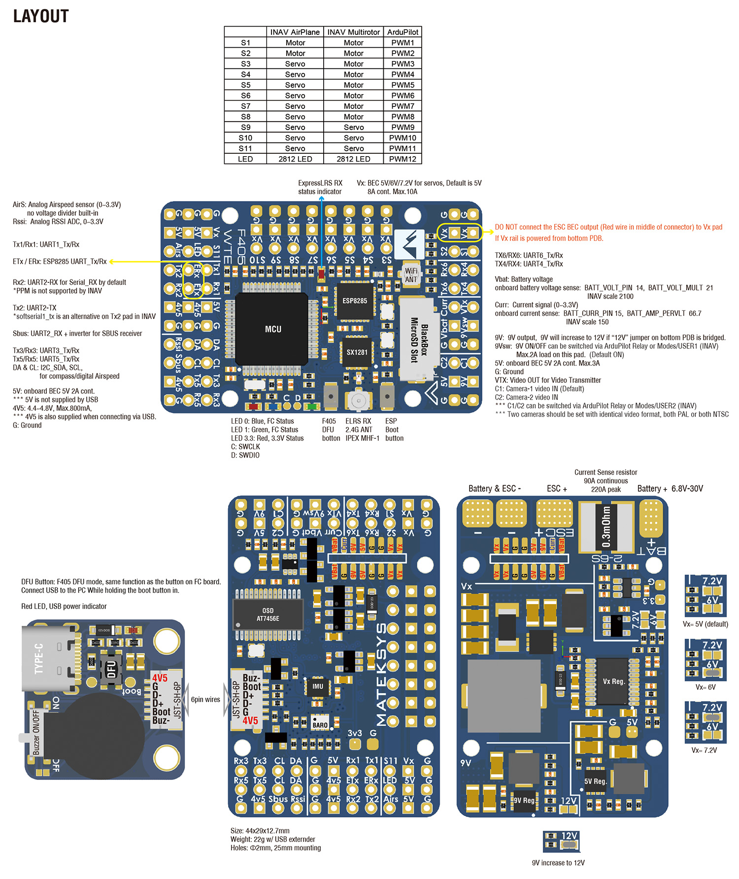
MCU: STM32F405RGT6, 168MHz , 1MB Flash
IMU: ICM42688-P
Baro: SPL06-001
OSD: AT7456E
Blackbox: MicroSD card slot
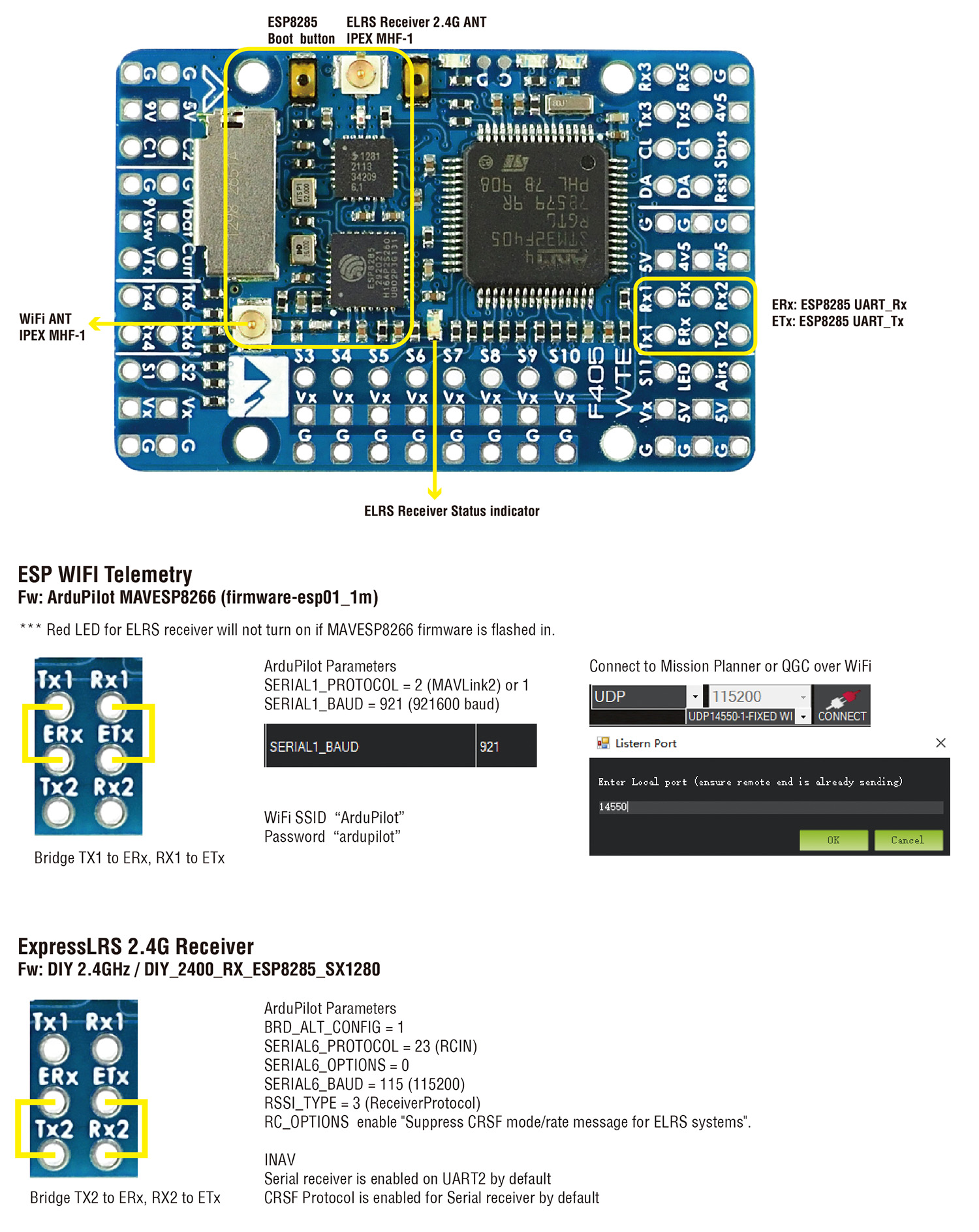
ESP WiFi Telemetry(MAVLink, 14dBm)
ExpressLRS 2.4G receiver(CRSF protocol, Telemetry 12dBm)
6x UARTs, 1x Softserial_Tx option(INAV)
12x PWM outputs
1x I2C
4x ADC (VBAT, Current, RSSI, Airspeed)
USB/Beep Extender with Type-C(USB2.0)
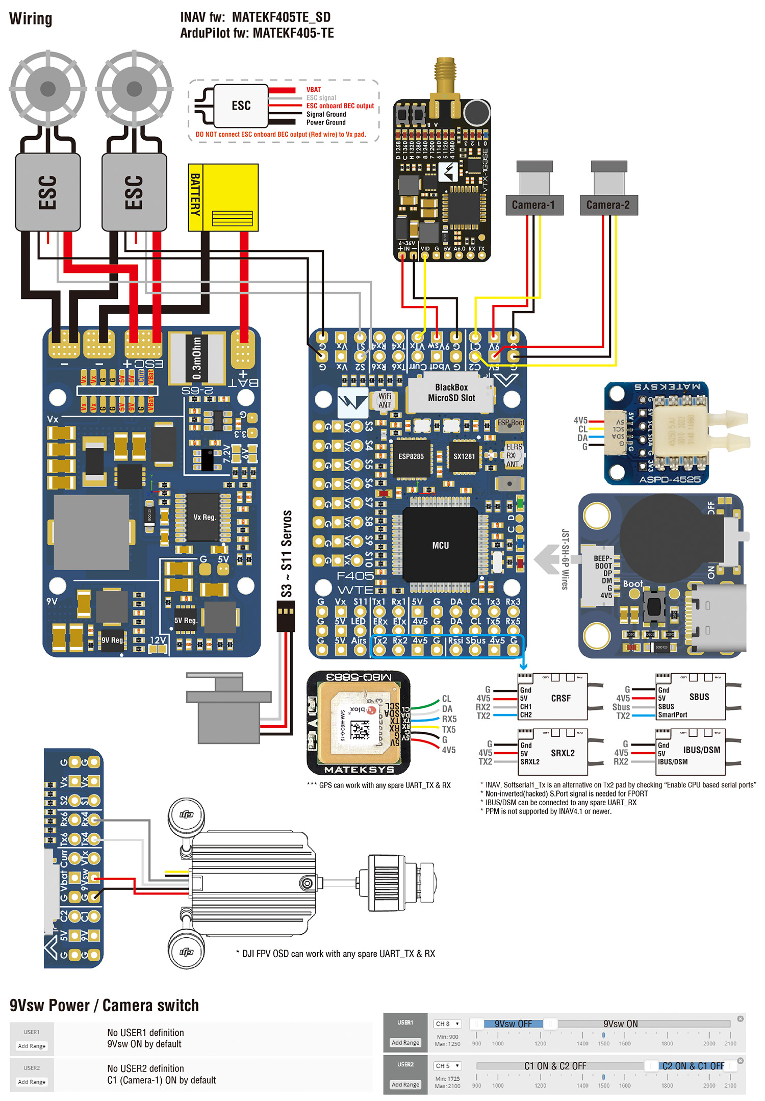
Dual Camera Inputs switch
9V(12V) for VTX power switch
FC Firmware
ArduPilot: MatekF405-TE
INAV: MATEKF405TE_SD (not available in INAV configurator 4.x)
PDB
Input voltage range: 6.8~30V (2~6S LiPo)
1x ESC power pads
Battery Voltage divider 1K:20K (Scale 2100 in INAV, BATT_VOLT_MULT 21.0 in ArduPilot)
Current Senor: 220A, 3.3V ADC (Scale 150 in INAV, 66.7 A/V in ArduPilot)
Sense resistor: 90A continuous, 220A peak
BEC 5V output
Designed for Flight controller, Receiver, OSD, Camera, Buzzer, 2812 LED_Strip, Buzzer, GPS module, AirSpeed
Continuous current: 2 Amps, Max.3A
BEC 9V /12V output
Designed for Video Transmitter, Camera, Gimbal ect.
Continuous current: 2 Amps, Max.3A
12V option with Jumper pad
for stable 9V/12V output, input voltage should > output voltage +1V
BEC Vx output
Designed for Servos
Voltage adjustable, 5V Default, 6V or 7.2V via jumper
Continuous current: 8 Amps, Max.10A
for stable Vx output, input voltage should > Vx voltage +1V
BEC 3.3V output
Designed for Baro / Compass module and external 3.3V peripherals
Linear Regulator
Continuous current: 200mA
Physical
Mounting: 25 x 25mm, Φ2mm
Dimensions: 44 x 29 x 12.7mm
Weight: 22g w/ USB/buzzer adapter
Including
1x F405-WTE
1x USB(Type-C)/Beep (Passive buzzer) Extender + 20cm JST-SH-6P to JST-SH-6P cable for USB extender.
2x IPEX-MHF1 2.4G Antennas
1x Rubycon ZLH 35V 470uF capacitor
Dupont 2.54 pins (Board is shipped unsoldered)
ArduPilot ESP8266 wifi telemetry
- Tool: ESP_NodeMCU-PyFlasher.exe
- Firmware: firmware-esp01_1m.bin
- Flashing with ESP_NodeMCU-PyFlasher
- Wire the ESP8285(ETx, ERx) into the USB-TTL adapter, with ETx on F405-WTE connected to the Rx on the USB-TTL, and ERx connected to the Tx of the USB-TTL. Wire 4v5 and GND of F405-WTE to 5V and GND of the USB-TTL
- Connect USB-TTL Adapter to PC while pressing and holding the ESP8285 boot button in.
- open ESP_NodeMCU-PyFlasher
- select Serial port of USB-TTL module, load firmware, select “Dual Output(DOUT)” and “Yes.wipes all data“
- click “Flash NodeMCU“
- after flashing, Power off , then power on F405-WTE by USB or Battery.
- Wait a few seconds, search WiFi SSID “ArduPilot”, and password is “ardupilot”
- Tips: Red LED for ELRS receiver will not turn on if MAVESP8266 firmware is flashed in.
- ExpressLRS AUX1-AUX8 are not full resolution CH.
- Flashing via WiFi
- Power on F405-WTE by USB, Receiver’s LED(Red) will blink slow at first, and after 30s, it should blink fast indicating it’s on WiFi Hotspot Mode.
- More detailed steps, pls refer this page.
- configurator 1.5.x or older, Target: DIY_2400_RX_ESP8285_SX1280_via_WIFI
- configurator 1.6.x or newer, Target: Generic targets used as a base 2.4 GHz –> Generic ESP8285 2.4Ghz RX
- Wire the ESP8285(ETx, ERx) into the USB-TTL adapter, with ETx on F405-WTE connected to the Rx on the USB-TTL, and ERx connected to the Tx of the USB-TTL. Wire 4v5 and GND of F405-WTE to 5V and GND of the USB-TTL.
- Connect USB-TTL Adapter to PC while pressing and holding the ESP8285 boot button in.
- configurator 1.5.x or older, Select the target DIY_2400_RX_ESP8285_SX1280 and “UART” for Flashing Method, set your bind phrase and Firmware Options and once done, click on Build and Flash.
- configurator 1.6.x or newer, Select the target Generic targets used as a base 2.4 GHz –> Generic ESP8285 2.4Ghz RX and “UART” for Flashing Method, set your bind phrase and Firmware Options , Check “erase before flash” and “Force FLash “.
- Tool: ESP_NodeMCU-PyFlasher.exe
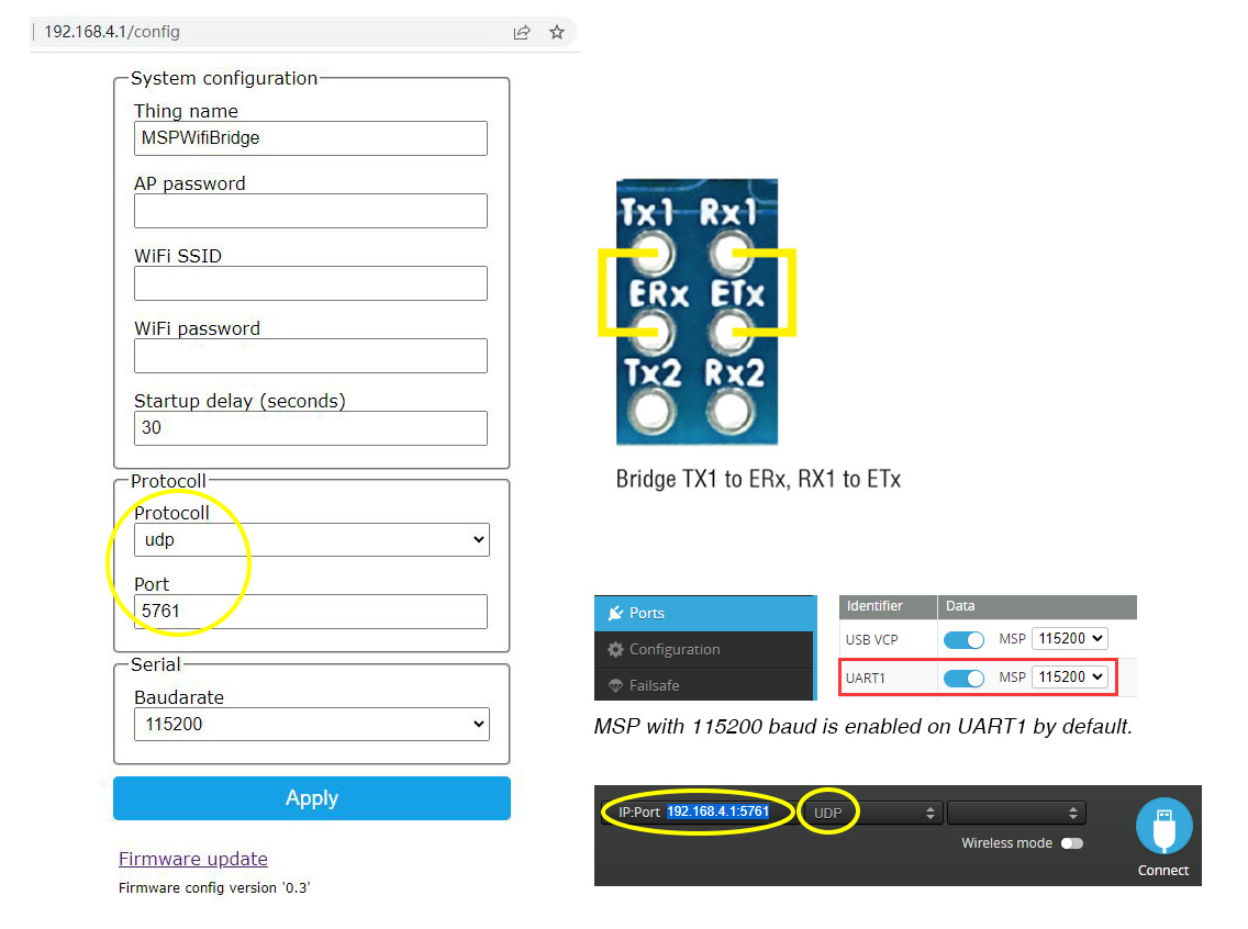
- Firmware: MSPWifiBridge_ESP-01.bin compiled based on github.com/Scavanger/MSPWifiBridge
- Flashing with ESP_NodeMCU-PyFlasher
- Wire the ESP8285(ETx, ERx) into the USB-TTL adapter, with ETx on F405-WTE connected to the Rx on the USB-TTL, and ERx connected to the Tx of the USB-TTL. Wire 4v5 and GND of F405-WTE to 5V and GND of the USB-TTL
- Connect USB-TTL Adapter to PC while pressing and holding the ESP8285 boot button in.
- open ESP_NodeMCU-PyFlasher
- select Serial port of USB-TTL module, load firmware, select “Dual Output(DOUT)” and “Yes.wipes all data“
- click “Flash NodeMCU“
- after flashing, Power off , then power on F405-WTE by USB or Battery.
- Wait a few seconds, search WiFi SSID “MSPWifiBridge”, and password is “123456789”
- If there is no automatic forwarding to the configuration page, go to http://192.168.4.1 manually. Standard login data: Username: admin, Password: 123456789
Δείτε Επίσης


Brand: Matek
Model: RC-026
FC Specifications
MCU: STM32F405RGT6, 168MHz , 1MB Flash
IMU: ICM42688-P
Baro: DPS310
OSD: AT7456E
Blackbox: MicroSD card slot
6x..


Brand: Matek
Model: RC-014
FC Specifications
MCU: STM32F405RGT6, 168MHz , 1MB Flash
IMU: ICM42688-P
Baro: SPL06-001
OSD: AT7456E
Blackbox: 16M Flash
5x UARTs, 1x Softseri..


Brand: Matek
Model: RC-015
FC Specifications
MCU: 100MHz STM32F411CEU6
IMU: BMI270 (SPI) or ICM42688P
Baro: SPL06-001 (I2C)
OSD: AT7456E (SPI)
Blackbox: No
2x Uarts
..


Brand: Matek
Model: RC-025
Specifications
Optical Flow: PMW3901
Lidar: ST VL53L0X (max. range 2 m)
Interface UART
Protocol: MSP
Working Range: 8cm~200cm
Field of v..